M34 and M34A1 Gun Mounts for 75mm main guns

Click on the picture for larger size
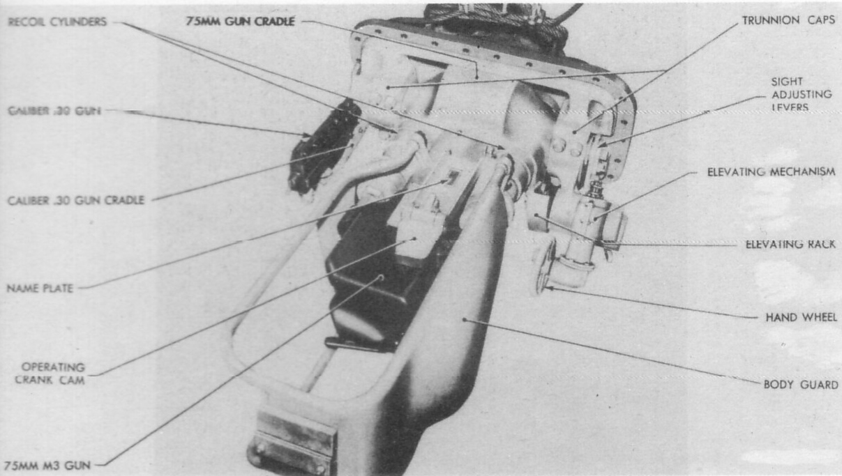
The M4 Sherman Tank series was initially equipped with what was termed the "Combination Gun Mount, M34." The above Tech Manual illustrations point out and name some of the components of the M34 Gun Mount.
Click on the picture for larger size
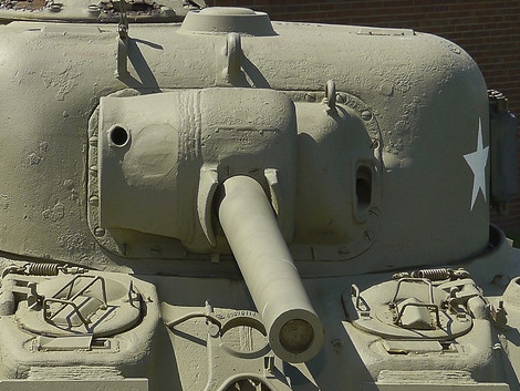
There is some confusion about the nomenclature of a couple of the components of the 75mm Gun Mount, so here we will use their "official" terms. The above photo shows the external components in question: the gun shield (inner casting, having part number D50880), and the rotor shield (outer casting with part number D51288). Note that the M34 Gun Mount was not equipped with a direct telescopic sight; instead fire was directed through the gunner's periscopic sight mounted in the turret.
Click on the picture for larger size
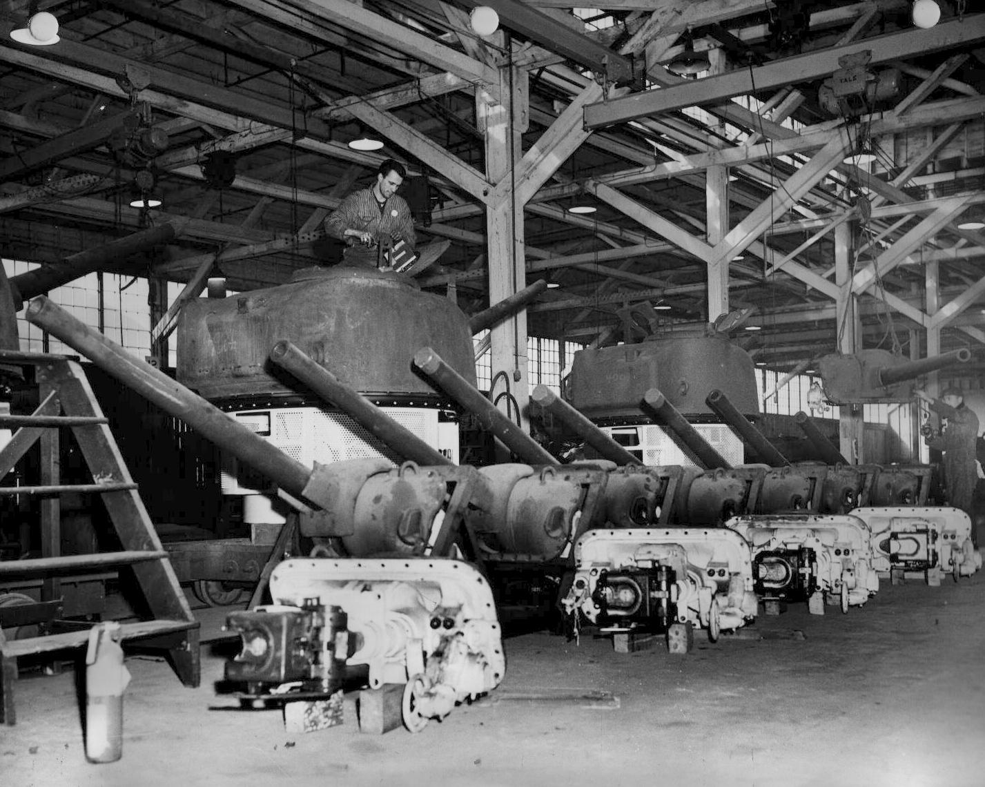
Pacific Car & Foundry was one of the firms that assembled Gun Mounts, and in the factory photo above, one can see inner and outer views of the M34 ready for installation.


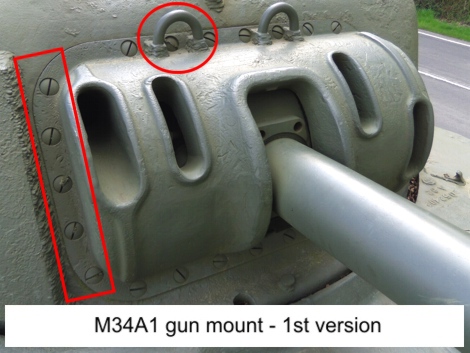
The earliest M34 gun mount design had the lifting rings on the gun shield mounted very close together (left-side photo). However, it was noted that if they got damaged & became bent, the lifting rings could interfere with the working of the rotor shield. All of the manufacturers but Fisher Body appear to have moved the lifting rings further outboard soon after they began production (right-side photo). In addition, a field fix was issued in July, 1942. However, there are enough period photos and surviving tanks still in the original configuration to indicate the fix was not universally applied.


Here we see some of the late 1942 improvements to the M34 gun mount. Note how a pair of protective "cheeks" have been added to the rotor shield casting to protect the gun from bullet splash. With the same purpose, a cast shield was created for the coaxial machine gun. The MG shield was issued as a modification kit, and shipped to Allied Forces in the Mediterranean Theater in Spring, 1943. These modifications can be seen on a Free French tank named "Duguay-Trouin" (2nd Cuirassiers Regiment), currently displayed at Dijon, France. Note that the gun shield lifting rings are in the later, "outboard" configuration, and are not welded on as was usual, but are part of the D50880 casting.

Technical problems with the gunner's periscopic sight, along with reports from the field, indicated a need for a direct telescopic gun sight. The M34A1 Gun Mount (discussed below) was designed for this purpose & standardized in October, 1942. However, it would take some months before the M34A1 could be mass produced & replace the M34 Gun Mount. In the interim, a "Quick Fix" kit was designed so that the telescopic sight could be retrofitted to the thousands of Shermans that had been built with the M34. The program was plagued by various delays, so that ultimately the kits were not available when needed before D-Day. Although there are quite a few surviving Shermans in the US that have "the M34 Gun Mount modified for installation of a coaxial telescopic sight", photographic evidence suggests that very few of these were sent overseas during WW II. The authors can only speculate that these kits were installed on Shermans remanufactured in 1945 or later. The above photos of an M4A3 in Dunkirk, Ohio show the cast "wing" and "endcap" pieces, as well as some of the cutting & welding needed to retrofit the telescopic sight to the M34 Gun Mount.

The
M34A1 Gun Mount first entered the production lines in March
1943 and appears to have completely replaced the M34 by April. The
new gun shield carries part number E5721, and
the rotor shield is part number D68454. Note how the rotor
shield is extended on each side to protect both the telescopic sight
and the coaxial machine gun.

The first version of the M34A1 gun shield had lifting rings & attachment flanges on the top, bottom & right side (left-side photo). The final version (right) eliminated the lifting rings, & moved the right side attachment points to the inside of the turret, thus dispensing with the outer flange on that side.


A transitional pattern for the M34A1 gun shield has been observed. It has the exposed flange but no lifting rings. Photos courtesy of Frank Louw (left) and Stephen Tegner (right).
M52 Combination Gun Mount for 105mm howitzer


In 1943,
tests were conducted to develop a 105 mm Gun Mount that could be
plugged into the basic 75mm turret shell. Standardized as the
"Combination Gun Mount, M52," the first M4(105)s were accepted in
February, 1944. Starting in May, M4A3(105)s were also produced.
The
external cast components of the M52 Gun Mount can be seen
above. Note how the lifting rings were part of the
distinctive 105 mm rotor shield casting (part number E6257). The
M52 design included provision for a canvas dust cover, and one can see
the 1944 (left) & 1945 versions of the dust cover
fittings in the photos above. The "look" went
from a bent rod with "buttons" (like on the bow MG dust cover fitting), to a
series of pads with little clips screwed into them. Also, a shutter to protect the
telescopic sight can be seen on the 1945 production rotor shield.

This photos shows the canvas dust cover, with the 1945 version of the dust cover fittings, but without the shutter to protect the telescopic sight.
M62 Combination Gun Mount for 76mm gun


The
M62 Gun Mount as installed in the T23 turret differed from the mounts
discussed earlier in that there was no rotor. The gun works were
protected by what was officially termed a "gun shield." This
was a casting three and a half inches thick, which
carried part number E6180.
Here are shown examples
of the E6180 Gun Shield, with the three types of 76mm
barrels. The earliest version (top left) was simply a straight gun
barrel. The
second (top right) was threaded to accept a muzzle brake. A collar was
provided to protect the threads, until the supply of muzzle brakes
caught up with production. The final version (bottom left), of
course, had the muzzle brake. In late 1944, fittings were
provided for a canvas dust cover (bottom left). The dust covers
themselves (bottom right) reached production in early 1945.
HOME