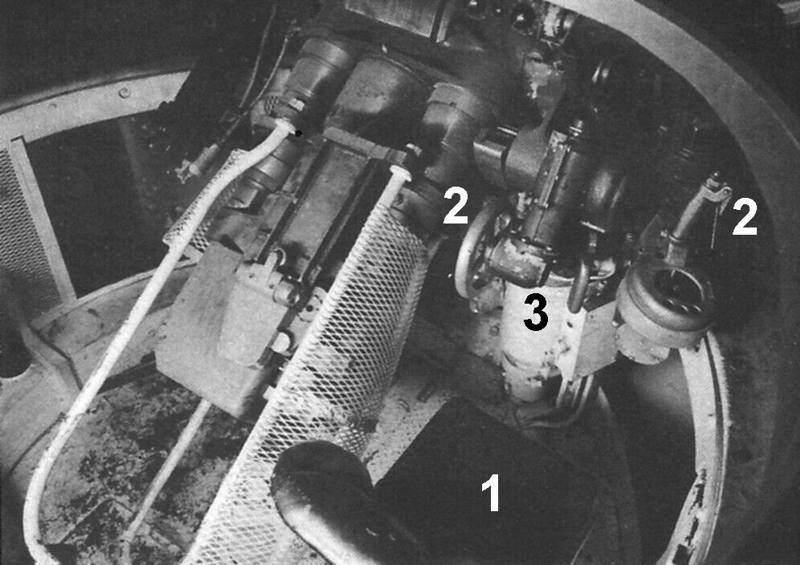
An unspecified M3 Medium
served as donor for the T6's lower hull, power train and numerous other
components. In the photo above dated July 2 1941, a bit of the M3's upper hull
(1) can be seen. The lower hull was completely stripped out. Work appears to
have begun on test fitting of the firewall (2) and one of the vertical fuel
tanks (3).

The M3 had a crew of seven,
which was reduced to five on the T6. In the above photo dated August 26 1941,
the driver's seat (1) can be seen to be installed on a platform raised off the
belly plate. The seat for the assistant driver (or bow gunner) (2) was installed
on a swivel affixed to the side of the hull. The swivel mount was replaced by a
pedestal mount on production Shermans. The assistant driver was not provided
with an overhead hatch on the T6. An escape hatch was installed in the belly
plate directly behind his seat (inset). Item 3 is the identification plate for
the "Mack Medium M3 Powertrain." Item 4 is the battery box. Item 5
shows the normal installation of the bogie units. For some reason, the middle
bogie on the right side was bolted on through some reinforcing bars (6).
 The
photo above was taken at APG on September 2, 1941, the day before
"presentation day" of the T6 pilot. It shows a version of the cast hull
that didn't "make the cut," possibly because the turret splash was only
provided at the front. The "C-H" logo cast on the left side in the rear
shows that this particular hull was produced by the Continental Roll
& Steel Company. As with most M4A1 small hatch upper hull castings,
the part number can be seen as E4153. This particular casting was the
company's first, serial number 1. We would note that the first
production M4A1 had C-H E4153 hull serial number 3, built to revision 7.
The SN 3 casting incorporated many changes, but still had the side
doors. They were simply blanked off by Lima Locomotive, since the side
doors had been eliminated from the design at a conference
on "presentation day." The chalked on numbers are thickness measurements
in inches at various points along the hull. At standardization of the
design, the armor protection was to be not less than 2 inches on the
front, 1 1/2 inches on the sides and rear, and 1 inch on the top deck
(roof). The information panel has it that the casting weighed 11,500
pounds.
The
photo above was taken at APG on September 2, 1941, the day before
"presentation day" of the T6 pilot. It shows a version of the cast hull
that didn't "make the cut," possibly because the turret splash was only
provided at the front. The "C-H" logo cast on the left side in the rear
shows that this particular hull was produced by the Continental Roll
& Steel Company. As with most M4A1 small hatch upper hull castings,
the part number can be seen as E4153. This particular casting was the
company's first, serial number 1. We would note that the first
production M4A1 had C-H E4153 hull serial number 3, built to revision 7.
The SN 3 casting incorporated many changes, but still had the side
doors. They were simply blanked off by Lima Locomotive, since the side
doors had been eliminated from the design at a conference
on "presentation day." The chalked on numbers are thickness measurements
in inches at various points along the hull. At standardization of the
design, the armor protection was to be not less than 2 inches on the
front, 1 1/2 inches on the sides and rear, and 1 inch on the top deck
(roof). The information panel has it that the casting weighed 11,500
pounds.

The T6 was rolled out for
presentation on September 3, 1941. Richard Hunnicutt, author of the seminal
work on the Sherman wrote, "Although the cupola was part of the wooden
mock-up, the writer has no evidence that it was ever installed on the pilot
tank." In fact, the cupola from the M3 Medium (1) was installed on
"presentation day," but in a conference later that same day, it was
decided to replace it with the commander's split hatch which became standard on
production Shermans. The conferees also determined that the hull side doors (2)
were to be eliminated, and that a rotating periscope would be retrofitted in
the turret roof in front of the loader's position. Note that the tank can be
seen to be "riding high" on the M3 type bogies. The interior stowage
arrangements had not been finalized, so that the T6 was not fully equipped on
September 3rd.

Various dignitaries posed with
the T6 on "presentation day." General Jacob Devers was head of the
Armored Force. Colonel William Hardigg was Director of the Proving Center,
which oversaw the T6 Project. General J.B. Rose was Commandant of Aberdeen
Proving Ground at the time. Note that the protectoscope (1) taken from the M3
Medium, was installed a little forward of center on the right side of the
turret, but toward the rear on the left. The grab bars (2) were eliminated with
the side doors. The round object (3) which served to protect the antenna mount,
was replaced with a ventilator on production M4A1s.
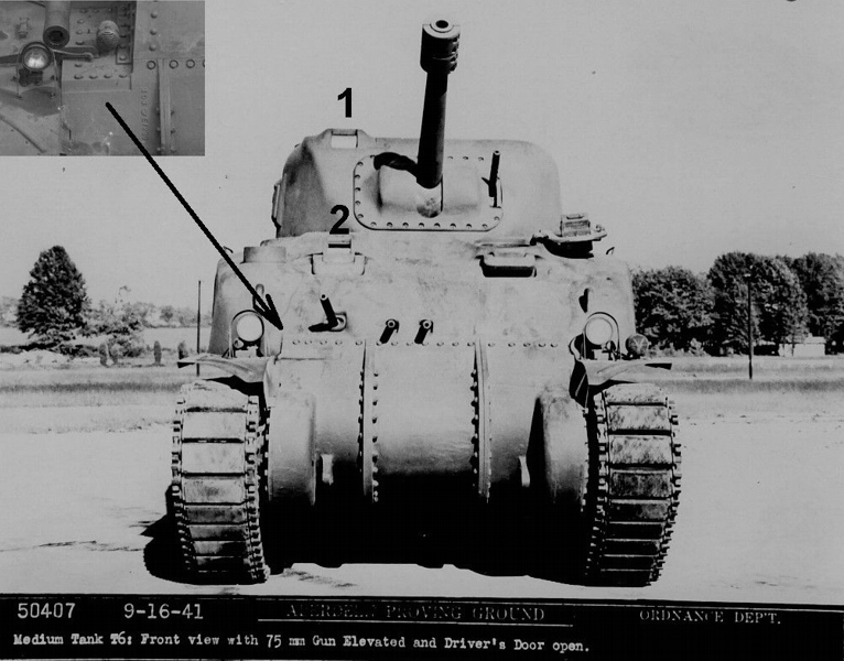
The T6 was photographed again
on September 16th. In this front view one can see that the M3 cupola was
removed, and that double counterweights were added to balance the short
barrelled M2 Gun. The sight rotor (1) was linked to the main gun. The assistant
driver was also provided with a sight rotor (2) linked to the bow machine gun. The
flexible weapons are shown elevated, and the designers quickly realized that
all of the various rotors were vulnerable to bullet splash damage that could
disable the guns. In adapting the M3 differential housing to the T6, it was
necessary to weld in a bolt strip extension to the right section. Until a
revised casting became available, early manufacturers of the Sherman were
shipped M3 differentials (inset) that they had to alter in house.

In this view, note the rear
contours of the T6 upper hull. This area of the casting was revised
significantly before the M4A1 entered production (inset). The T6's tool
stowage was similar to the M3's. M3 Medium production commenced in June
1941. Less than 300 units had been accepted by the time the T6 was
presented in mid-September. As the M3 entered service, users began
to report that the "pepper pot" exhausts (1), which vented
up directly under the engine deck, were causing an intense heat
buildup in the engine compartment which degraded the performance of the
engine. Furthermore, the engine deck often got so hot that it became a
danger to the crew (or riders). In early 1942, the Ordnance
Department tried to remedy problem without disrupting M3 production by
means of a "Quick Fix." The pepper pots were replaced with a pair of
fishtail exhausts that directed the hot exhaust out and away from the
vehicle. By May 1942, the R-975-EC2 engine, which ran on
90-octane aviation fuel, was replaced in production by
the R-975-C1 which ran on the 80-octane gasoline
preferred by the Army. The exhaust system was redesigned so that the
exhaust pipes were centrally mounted under the upper real plate. Aside
from the T6, about 70 of the first M4A1s were accepted with R-975-EC2
engines, but it was ordered that they be replaced with
the R-975-C1 before entering service.


Click on the photos for larger size
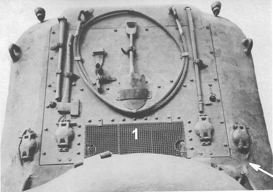
The overhead photo on the left
provides another view of the rear contours of the T6. It was known that
the M3's air intake (1) was vulnerable, and an armored cover was
designed for use on production M4s and M4A1s. The photo on the right
shows the intake cover in the open position on the very first production
M4A1. This change forced a rearrangement of the original M3 Medium tool
stowage, which, as is obvious in the photo on the left, was extremely
inconvenient when the engine decks had to be removed for service.
Comparing the two photos, one can see that the T6's cast-in bullet
splash was interrupted, whereas it was continuous back to the fuel cap
covers on production M4A1s. Note that the rear hull ventilator (2),
standard on all Shermans, is absent on the T6. The locking pins that
secured the armored fuel cap covers were in the M3 "short and straight"
configuration, whereas they were longer and angled on production
Shermans.


The overhead photos compare
the T6 (left) with the third M4A1 (Serial Number 7) made by Pressed Steel Car.
Without a hatch, the assistant driver's vision was restricted to straight
ahead, even under non combat conditions. In the T6's Daily Logs for October 1
1941, the designers did away with the bow machine gun sight rotor, and provided
the assistant driver with a hatch configured as a mirror image of the driver's.
The designers also determined to provide the main gun with a rotor shield (1),
and the bow machine gun with a ball mount (2) before series production began.
The headlamps (3) were relocated to the hull. The lifting handle (4) on the T6's
driver's hatch can be seen to be mounted towards the rear and on an angle. This
"early" position carried over to some of the first production
Shermans. PSC Serial Number 7 had had its handles (5) relocated to the standard
position by the time it was photographed in December 1942.

The photo above provides
an interior view of the driver's hatch and the direct vision device. As
mentioned previously, the General Steel Company cast the T6's upper hull, and
their distinctive logo, a G inside a shield, appears on the hatch. It can
be seen to have a casting part number of D-50884. When it was decided to
provide the assistant driver with a hatch, the part number remained the same,
but a "B" suffix was added to the driver's hatch, and an
"A" to the assistant's. Although the direct vision appears to provide
protection, the designers noted that small gaps permitted the entry of bullet
splash. Ultimately, direct vision was ordered eliminated on June 24 1942 for
cast hulls and August 13 for welded hulls. It would take some months before the
redesigned drivers' hoods could enter production, and several thousand Shermans
were built with direct vision.

For voice communication, an
SCR 508 (or subsequent improvement) was mounted in the turret bustle of
standard US Shermans. The T6 was built to be a command tank, and the photo
above shows the installation of the additional SCR 506 long range radio. The
radio can be seen to be partially blocking the side door, but, of course this
was not an issue, since the doors were to be eliminated. It is to be noted that
production Shermans were built as standard tanks. Command tank radio
installations were retrofitted by the Signal Corps as conditions required.

The photo above illustrates
the antenna problem encountered with the command tank's radio. Reports from the
field were coming in to the effect that greater ventilation was needed for
crews inside the M3. In November 1941, it was determined that the Sherman would
be equipped with 3 ventilators - 2 in the hull and 1 in the turret. The protuberance circled
was originally made as an antenna bracket, but served as a location for one of
the three ventilators on the M4A1.

The novice Army designers had
a certain obsession with firepower. The M2 and M3 Medium tanks were described
in press releases as "rolling fortresses," since they were bristling
with guns. An unfortunate consequence of this was that the T6 was equipped with
a pair of fixed .30 cal machine guns, as shown above. The designers appear to
have been reluctant to concede that these were wasteful and superfluous, but
the fixed guns were finally eliminated in early 1942. Only Lima Locomotive,
Pressed Steel Car and Fisher Body produced a few of their first Shermans with
the fixed machine guns installed. On subsequent units, hulls already produced
with the MG holes, had them filled in by welding.

The challenge in the
development of the US Medium Tank was to design a superstructure that could
carry a turret large enough to accommodate three men, and mount a 75mm gun. For
this purpose, it was thought that the turret ring would need to have an inside diameter
of 69 inches. In retrospect, this was one thing the designers "got
right" from the start. It was determined that the turret of the new Medium
Tank would be cast armor, while the upper hull would be of either welded or
cast armor construction. Above shows a left rear view of the T6 turret. The M3
type protectoscope (1) was replaced with a solid door, and the pistol port on
the right side was eliminated from the design in late 1941. Originally, the T6
turret did not have lifting rings (2). These were added to the turret and gun
shield during development, and became standard. The turret basket was encased
in steel mesh. It wasn't until early 1943 that this was recognized as a safety
issue, as the mesh "trapped" the turret crew, and isolated the
drivers. In April, work was begun to redesign ("skeletonize") the
turret basket. In August 1943, as part of a more comprehensive "Quick
Fix" Modification, the mesh was instructed to be removed from existing
Shermans.

In this unusual view of the
turret casting, one can see how the gun shield, sight rotor and commander's
cupola were bolted on. It was immediately decided to add a periscope for the
loader. A little later, a ventilator was added to the design. Their future positions
are shown in black. A Lima Locomotive Memorandum dated January 23, 1942 stated
that only the "first 30 tanks using Rotor Device." Later turret
castings had been revised to incorporate a gunner's periscope. As best we can
tell, the first 10 M4A1s produced by Pressed Steel Car were the only other
Shermans that were accepted with sight rotor turrets. The turret's height was
about 3 feet, and the armor basis was 3 inches on the front and 2 inches on the
other vertical surfaces. Although it underwent numerous revisions, the basic
shape of the T6 turret was used on 75mm and 105mm Shermans until the end of
production in mid 1945.

In this view through the
commander's hatch opening, note the brackets (1) installed in the turret
bustle. They could accommodate either the US or British standard tank radio. The
commander's (2) and loader's seat (3) were affixed to the turret basket wall,
and were height adjustable. A bit of the 75mm gun's breach and breach guard (4)
can be seen. With only one hatch in the turret, the breach guard presented an
obstacle to the loader as he attempted to escape in emergency situations. During
the initial design work, a loader's hatch was considered, but rejected in the
interest of simplicity. As a result of numerous combat reports, a loader's
hatch was added as a standard item on Sherman turrets in late 1943. 12 ready
rounds can be seen mounted to the wall of the turret basket. Ready rounds were
very popular with tank crews, but were extremely vulnerable.
The gunner's seat (1) was
mounted to the turret basket floor directly in front of the commander's
station. The gunner was provided with manual elevating and traversing controls
(2), along with a power traverse mechanism (3) that was considered one of the best
features of the tank. A gyrostabilizer was also provided that, in theory,
permitted firing of the main gun while on the move. Unfortunately, the
technology was not quite ready. The device was too complicated for average
crews to adjust and maintain and, in practice, it was mostly unused or
disconnected. The turret was designed to carry the 75mm gun as seen here.
However, the gun mount was "so designed that alternate armament may be
used." Initially, the British intended to employ their 6 pounder gun, but
trials and actual combat with Lend Lease Grants, clearly demonstrated the
superiority of the 75mm. Later tests showed that the turret could accommodate a
105mm Howitzer, but that it was too small to mount a 76mm gun with proper crew
efficiency. The 69 inch turret ring made it possible for the Sherman to accept
a larger turret without any major alterations to the existing hull. In January
1944, a larger turret for the 76mm gun was introduced in production.

The "Military Characteristics" defined for the improved
Medium Tank did not list a specific power plant or fuel type. Due to 1930s' budgetary constraints, no effort had been made to design a
dedicated tank engine. Thus, the T5 series and the succeeding M2 and M3 Medium
Tanks were powered by an "off the shelf" 9 cylinder radial aircraft
engine that was widely used by the Army Air Corps, and had a proven record of
reliability. Designing the US Medium Tank around a radial engine dictated that
the tank would sit about a foot higher than would have been the case had a comparable
in line or vee type engine been available.


As the US Military commenced
its massive build up in the early 1940s, materials priority appears to have
been given to the Navy and Air Corps. Recognizing that there would be a
critical shortage of aircraft engines, the Army turned to the automotive industry
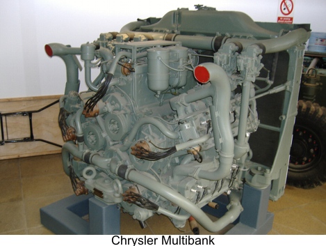
for alternate power plant designs. Chrysler quickly presented an expedient
which combined five 6 cylinder auto engines in a star configuration. Perhaps
reflecting the desperate nature of the tank engine situation, the Army accepted
the so called "Chrysler Multibank" for production on both the M3 (109
M3A4s) and the M4 (7499 M4A4s). It must be noted that the outlandish design
actually gave good service. General Motors married two of its 6 cylinder diesel
truck engines to produce an effective power plant that was introduced on the M3
Medium series in January 1942, and remained in production until May 1945 on the
M4A2 Sherman. Finally, the Ford Motor Company presented an experimental 500 HP
V-8 engine that soon became the preferred power plant of the US Army. It was
used to the end of production on the M4A3 Sherman, as well as on its
replacement, the M26 Pershing. Photo of the Chrysler Multibank courtesy of "BearGrease".

In August 1940, the British
Tank Mission was authorized to place an order for 1500 M3 Medium Tanks
"modified to the British [Grant] turret." They did not care for the M3's
design, but were desperate for tanks, since they had lost most of their armor a
few months earlier during the Battle of France. Also in August, perhaps not
trusting that the Americans could come up with an acceptable replacement, the British and Canadians set
about to design their own version. In January 1941, it was determined that the
"M4 Cruiser to be made by Montreal Loco Co." would be built on the
lower hull of the M3 Medium, and like the T6, would employ a cast upper hull
and turret. It was intended that 90% would mount the 6 pounder (57mm) firing
solid shot, while the remainder would carry the 75mm for close support roles.
Christened "Ram," the pilot was completed in June 1941, and is shown
above undergoing tests at APG in August. The 6 pounder was not yet available,
so a 2 pounder was installed on the pilot, as well as the first 50 production
units.

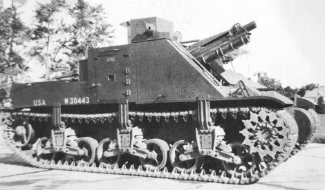
Both the Ram and the T6
achieved the goal of redesigning the M3 Medium so that the main gun was mounted
in a revolving turret. If the redesign is considered a race, the Commonwealth
team won, as they completed the Ram pilot 3 months before the T6, and 110 units
had been manufactured before the first production Sherman was accepted on the
last day of February 1942. However, the Ram was designed around the British 6
pounder gun. The turret ring was only 60 inches in diameter, and crew
conditions inside the turret were described as "cramped." This would
only have been exacerbated had it been decided to fit the Ram with a 75mm (or
larger) gun. Ultimately, the T6 was considered by all parties to be the better
design. While the Ram was not used as a "combat tank," it served
admirably as a training vehicle for the rapidly expanding Canadian Armoured
Force. When sufficient supplies of Shermans became available, Rams were
converted to various "funny tank" roles such as Command and
Observation Post vehicles, and most notably, "Kangaroo" armored
personnel carriers. 1950 Rams were produced from December 1941 through July
1943. The photo above shows the assembly line at Montreal Locomotive on October
26, 1941.

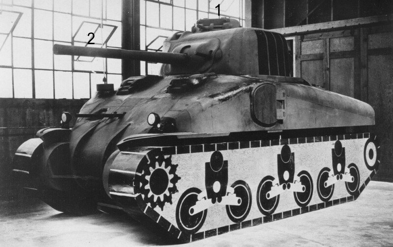
An unfortunate gap exists in the history of the Sherman's development.
To date, it would appear that no photos have surfaced showing the welded hull
pilot that was assembled at Rock island Arsenal. (An RIA teletype dated October
18, 1941 stated that the pilot was "now under construction here.")
For the time being, we will have to make due with an image of a model
photographed at Pullman Standard on November 27, 1941. The model differs from
the T6 pilot in that it was made WITH the assistant driver's hatch, and WITHOUT
the side doors. The turret appears to be identical to the T6's after the M3
cupola had been eliminated, but before the split hatch was installed. The
original T6 gun shield was replaced with the improved M34 gun shield (1),
although the M34 rotor shield was not installed on the model. A single
ventilator (2) can be seen next to the driver's hatch. In production, small
hatch welded hull Shermans would have 4 ventilators: 1 beside each of the
drivers' hatches, one on the turret and one inside the turret splash on the
right rear. We are hoping some photos or a report about the welded hull pilot
will be found eventually. It is possible that it was shipped to Pullman or
another firm for use as their production pilot.

A 1-piece differential housing
was designed at the same time as the T6. The prototype was shipped to APG in
early 1942, and installed on the T6 in March. It was intended that the
simplified 1-piece housing would quickly replace the 3-piece, but some of the
power train manufacturers, including Chrysler, stated that they could not
retool without disrupting production. Thus, the 3-piece differential housing
continued in use alongside of the 1-piece, and was not completely replaced
until the end of 1943. Note that the prototype had a slightly raised
"lip" well forward of the bolt strip. In this photo, it would appear
that a section of cast armor containing the fixed MG apertures was welded into
the hull. Also, note the added MG dust cover fittings. The bow MG dust cover
became standard on Shermans by the Fall of 1942.

As Sherman production ramped
up in the Summer of 1942, the "M4, #1, Shop Pilot" was used in
various tests, including steel track trials. The mishap that was photographed
on July 11 1942 permits a good view of some of the changes made to the T6. A
standard M4 / M4A1 armored air intake cover (1) was added. The turret was
retrofitted with a number of items, including the commander's split hatch (2),
blade sight (3), lifting rings (4), ventilator (5), spot light fitting (6) and
(hole for) the loader's periscope (7). The T6's original short M2 gun was
replaced with the M3 gun. Most likely the entire original gun mount was changed
out for the standard production M34 Combination Gun Mount. Note how the
original T6 gun shield was replaced with the M34 gun shield (8), although the
M34 rotor shield was not added.

In this view one can see that the original pepper pot exhaust was
replaced with the so called "high" exhaust pipes (1) and the externally
mounted air cleaners (2), indicating that the T6's original R-975-EC2
engine had been exchanged for the improved R-975-C1 engine. The "round"
as opposed to "square" Vortox air cleaners shown here are not seen in
period photos until the end of 1942, so these may have been test parts.
Indeed, "Tests of Vortox EX3912B Air Cleaner, Round Body Type, Proposed
as Substitute on Medium Tanks M3 and M4" were conducted at APG in July
1942 which corresponds to the date of this photo. It was hoped that the
12-inch diameter, 22.5-inch-high round cleaners would provide a “slight
boost in efficiency,” but they provided “no advantages” over the
squares. Nonetheless, they were found to be acceptable substitutes for
the production square Vortox 3800-D cleaners. Just below the air
cleaners, it can be seen that the pepper pot holes were blanked off (3).
Production hull castings were extended down about 8 inches in the rear
directly over the tracks. The open area (4) was blanked off, and an
oblong hole was machined out on the upper hull to provide for grouser
storage. Note the rivets on the belly plate of the T6's M3 Medium lower
hull. The military characteristics of the M4 called for "fabrication by
welding" of the lower hull. While the vast majority of Sherman lower
hulls were welded, Pressed Steel Car continued to use riveted lower
hulls until the Spring of 1943. We have found no explanation for this
exception, but it may be that PSC was tasked with using up the remaining
supply of M3 Medium riveted lower hulls once production was terminated.
Company correspondence mentions that the interior protruding rivets of
"our special lower hull" necessitated a slight divergence in the
standard arrangement of the Sherman's internal stowage.
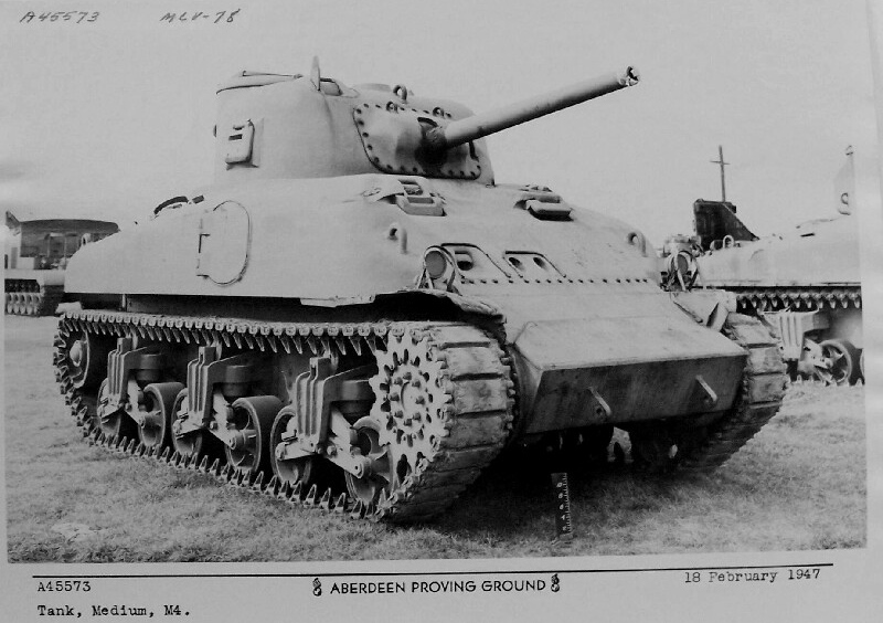
In early 1943, APG was directed to design some Field Modification Kits
that could provide the differential housing with greater protection. The
welded construct shown above was rejected because it extended beyond
the front of the tank. After its days as a test vehicle, the T6 Pilot
was sent to the Ordnance Museum for "historic purposes." The photo above
is dated February 1947, and is perhaps the last known image of the
tank. Notice that the tank's original gun shield was reinstalled, with
lifting rings retrofitted. The T6 may have been destroyed along with
many other of the museum's AFVs during a Korean War era scrap drive. The
museum's curator at the time, Colonel George Burling Jarrett, would
have been acutely aware of the historical significance of the first
Sherman, and it is hard to believe that he would have permitted this had
he had a say. We continue to hold out a small hope that it is stashed
away somewhere at APG.
HOME