The original or "1st
Generation" Sherman design featured a 75mm gun
mounted in a cast turret. The hull could be either a single piece
casting or a welded assembly. The welded hull was designed with a
multi-part glacis with a 57° slope and protruding drivers' hoods
with "small" hatches. It was necessary to increase the length of the
M4A4's welded hull by 11 inches in order to accommodate the large
Multibank engine. Some of the first Shermans produced were installed
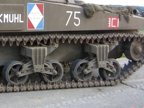
with the type of Vertical Volute Spring Suspension [VVSS] bogies used
on the M3 Medium Tank series. Chrysler designed the heavier duty
bogie units seen here to support the Multibank engine's greater weight.
For convenience, we refer to these as "M4 bogies," because, as quickly
as they could be produced, they replaced the older M3 type bogies, and
became standard on all M4 series Shermans built with VVSS. From start
to finish, M4A4s were installed with power trains that were protected
by 3-piece differential housings. These had been designed originally
for the M3 Medium, but were carried over to the M4 series. It was
intended that they be replaced by a simpler and stronger 1-piece
housing which entered production in mid 1942. However, some power train
manufacturers, including Chrysler, stated they could not retool for the
new configuration without it creating a serious slowdown in Sherman
production. Consequently, it was agreed that Chrysler would complete
its run of M4A4s with the 3-piece differential housing, and switch over
to the later, sharp-nosed type of 1-piece housing when it started
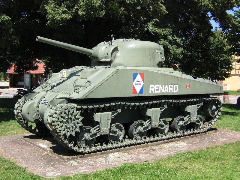
production of the M4 Composite in August 1943. The photo above shows
Serial Number 18157, one of the M4A4s provided to the French as Lend
Lease. "Duguay-Trouin" served with the 2ème Régiment de
Cuirassiers of the 1ère Division Blindée and was reported
to have been knocked out on 6 September 1944 during the Battle for the
Liberation of Dijon, where she now stands as a monument and memorial.

In a "side shot," the gap (arrows) between the road wheels is a good
recognition feature of the elongated hull of the M4A4. Pierre-Olivier
measured the gap and found it to be about 10 inches (25.4 cm). On other
Sherman type hulls, P-O measured the gap at about 3 inches (7.6 cm).

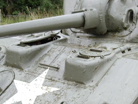
The earliest M4A4s were assembled with drivers' hoods with direct
vision slots such as shown on the left on USA 3057449, which was one of
the two M4A4s shipped to the USSR for evaluation. It was preserved and
is now on display at the Kubinka Tank Museum near Moscow. Testing
revealed that the direct vision slots were ballistic weak points, and on
13 August 1942, the Ordnance Department ordered them eliminated from
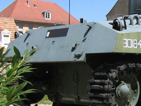
the design of the welded hull Sherman. The reconfigured drivers' hood
castings were elongated and included additional periscopes in front of
the hatches. Some lead time was needed to secure the new drivers' hood
castings. At present, our counting heads method suggests that the
transition from direct vision to the elongated drivers' hoods was
started and completed by Chrysler in November 1942. The right-side image
shows the elongated drivers' hoods on "Orléans II," Serial Number 17684
another combat casualty of the 2ème Régiment de Cuirassiers. This M4A4
serves as a monument in Beaune, France where she was KO'd on 7 September
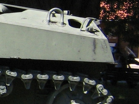
1944. It is thought that all of the drivers' hood castings used on all
of the M4A4s, both direct vision and elongated, were so called "wide"
drivers' hoods that were mirror images of each other.
In this front shot of "Duguay-Trouin," the weld seams are quite obvious,
permitting us to show the multi-part construction of the 57° glacis of
the M4A4. Sections 1 and 2 are armor plates. Section 3 is a casting that
includes the bow machine gun socket. The right (4) and left (5)
drivers' hoods are castings that protruded out from the glacis. We refer
to these as "wide" drivers' hood castings, because the inner sections
of the castings extended out and were joined together at the center
(arrow) to form part of the upper glacis and even a bit of the front
turret splash. The Ford Motor Company also used "wide" drivers' hood
castings in production of its M4A3s. Counting heads suggests that the
other manufacturers of 57° welded hull Shermans used "narrow" drivers'
hoods that were castings of just the hoods and were about 18 1/2 inches
wide. Note the distinctive shape of the cast antenna bracket (6) seen
here. This piece appears to have been used from start to finish on the
M4A4.
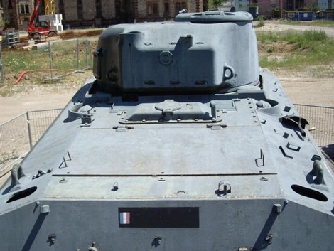
Above is a photo of M4A4 USA 3019152 taken at the Chester Tank Depot
shortly after the tank was processed and sealed for overseas shipment.
CTD carefully packaged the tools, guns and other "On Vehicle Materiel"
[OVM] into the wooden crates lashed to the engine deck. In this view,
one can see the shape and slope of the M4A4's upper rear hull plate.
M4A4s were built with a pair of grouser compartments accessed through
oblong holes. A few of the earliest units were shipped with the grouser
compartment holes blanked off. However, it was found that the fuel tanks
of the first M4s, M4A1s and M4A4s suffered an excessive heat condition,
which caused melted solder joints and other fire hazards. This was
remedied by the addition of a pair grouser compartment covers with air
inlet grills (1 and inset) that permitted greater air flow to the fuel
tanks and throughout the engine compartment. The sheet metal object
hanging below the upper rear hull plate is the engine exhaust deflector
(2), introduced by Chrysler in January 1943. A Field Modification Kit
was released in July 1943 which provided deflectors for retrofit to
earlier production M4A4s. For servicing of the engine, the deflector
could be pivoted up and secured to the upper rear hull plate by a pair
of locking pins (3).
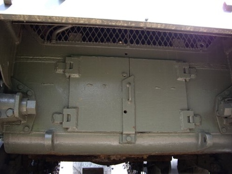
The M4A4's lower rear hull section was the only one of the Sherman
series that was mounted vertically to the lower hull "tub." Access to
the engine was provided by a pair of armored doors (1). The flange (2)
welded to the right-hand hand door did not span the entire height of the
doors as was the case with other "doored" Shermans but was abbreviated
as seen here. It can be noted in the photo that the lower rear hull
"plate" was not a single plate but was assembled using two plates (3) on
either side of the doors welded to an upper plate (4) that was cut out
for air intake and fitted with a wire mesh screen. This assembly was
welded to a cast, quarter round transition piece (5) that joined it to
the belly plate. On the examples we have been able to examine, the
towing "bosses" or lugs (6) are not welded on like most other Sherman
types but are part of the quarter
round transition piece casting. We can confirm this statement in the
M4A4 Technical Manual: "The vehicle serial number is stamped on each
boss (two front and two rear) to which the towing shackle is attached to
the hull." In any case, counting heads suggests that this lower rear hull configuration was used on all M4A4s.
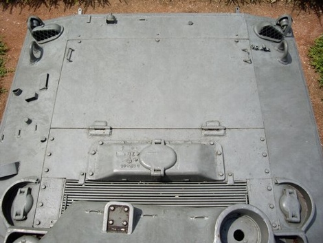
The M4A4 engine deck layout is shown above on "Austerlitz" a January
1943 production unit that was a combat casualty of the 2ème Régiment de
Chasseurs d'Afrique, 1ère Division Blindée. "Austerlitz" is on display
as a monument in Mulhouse, France, not far from where she was KO'd on 23
November 1944. The rearmost section (1) of the engine deck was welded
to the hull, so was not removable. The lifting handles (2) on the center
section were oriented side to side on some of the first M4A4s but
appear to have been reoriented front to back sometime during August
1942. The massive radiator protruded above the engine deck so that a
cast armor blister (3) was required to protect its top section. A
flattened armored cover (4) was mounted over the radiator water filler
point. The air intake grill (5) was made up of 17 closely spaced steel
rods. The short and long plates (6) just in front of the air intake
grill served to protect the turret race from bullet splash. This example
is missing the "grouser compartment covers with air inlet grills" or
"air scoops," so we see the oblong holes (7) that provided access to the
grouser compartments. Despite the extra track length needed for the
elongated hull, the M4A4 Technical Manual lists "(26)" for the number of
grousers carried, the same as other Sherman types.
HOME