End connectors for Vertical Volute Spring Suspension (VVSS) tracks
Introduction :
A Sherman track is made of shoes. A shoe is an assembly of one link, two connections (a.k.a. end connectors), two wedges and two nuts.
The track link pins were connected by means of end connectors which were held in place by a bevelled wedge nut. The nut is part number 503330 and the wedge is part number A176090. Because of this slight bevel the track links were forced to curl inward. The end connectors were made of cast steel with integral guide horns.
There were at least three standard end connector types. They come in two basic shapes, one with a narrow guide horn (for 1-1/8" and 1-1/4" diameter pins) and one with a wide guide horn (1-1/4" diameter pins).
The standard end connectors can be seen with a rectangular wedge hole or an oval wedge hole.
Standard End Connectors
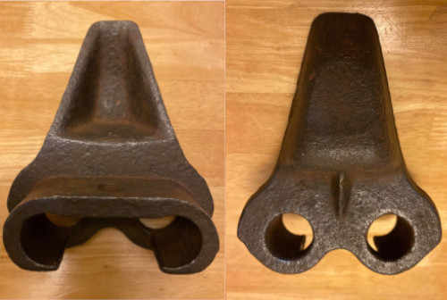

Narrow guide horn
pin diameter: 1-1/8"
Only fits on T41 and WE210 track links
Thinner bottom end, long and thin strengthening rib
Seen on M3 Medium tanks and on "Michael", the 2nd production M4A1(75) in Bovington
Photo courtesy of Richard Stickland

Narrow guide horn
pin diameter: 1-1/8"
Only fits on T41 and WE210 track links
Thicker bottom end, shorter and thicker strengthening rib

(narrow)
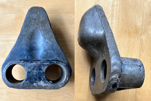
Narrow guide horn
pin diameter: 1-1/4"
Fits on every track link, except T41 and WE210

Narrow guide horn
pin diameter: 1-1/4"
Alternate to the C55592 end connector, rarely seen.
Photos courtesy of Richard Stickland.


(wide)
Wide guide horn
pin diameter: 1-1/4"
Fits on every track link, except T41 and WE210.
The end connector with wide guide horns do no appear on WW II Shermans.

Extended End Connectors
According to Mike Canaday, the
official nomenclature in the Standard Nomenclature List for the M4A3
76mm (ORD
9 SNL G-205) from the 1950's lists the actual official US Army name of
the part
in question is 7055614
Connector, track link, outer (Duck-bill). This
part is listed with the T48, T49, T51, T54E1, T56, T56E1, T62, and T74
tracks,
and NOT with the T41, T47E1, or the "CUFF TYPE".

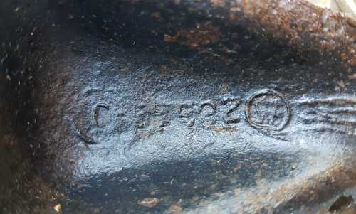
The photos show EEC as fitted on a M4A3(75) W currently displayed in Bastogne (Belgium).


The photos show EEC as fitted on a M4A2(75) currently stored at the Saumur Tank Museum (France).
The photos show EEC as fitted on a M4(75) currently displayed in Wibrin (Belgium).
The three photos show EECs as fitted on a M4A1(75) currently displayed in Bayeux (France).


On the first variant, the "dip" is straight, on the second variant it looks like a hook.
The photos show EECs as fitted on a M4A4(75) currently displayed in Oosterbeek (Netherlands).


The photos show EECs as fitted on an M4A1 75mm on a fire range in Eastern France.
Combat use of this type of EECs is confirmed by a photo showing a tank of the 6th Armored Division in Nancy area, in October, 1944.

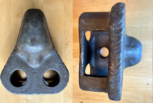
Note that there were 2 methods to fit these extended grousers on tracks.
The first method was the standard one consisting of bolting the grouser on the track, using holes in the track pins.
The second method, used for tracks that didn't have holes in the track pins, consisted in welding 2 wedges to the grouser (as seen on the grouser on top of the picture), and bolting the assembly to standard end connectors.